• +965 51122049
L298P Motor Shield

L298P Motor Shield

KWD4.500KWD4.500
0%Off

L298P Motor Shield


Share:

L298P Motor Driver Shield Features

Today, DC motors are used in the manufacturing many tools and equipments. So, speed and direction control of these motors is very common.

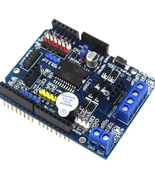
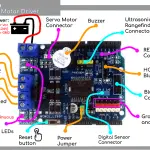
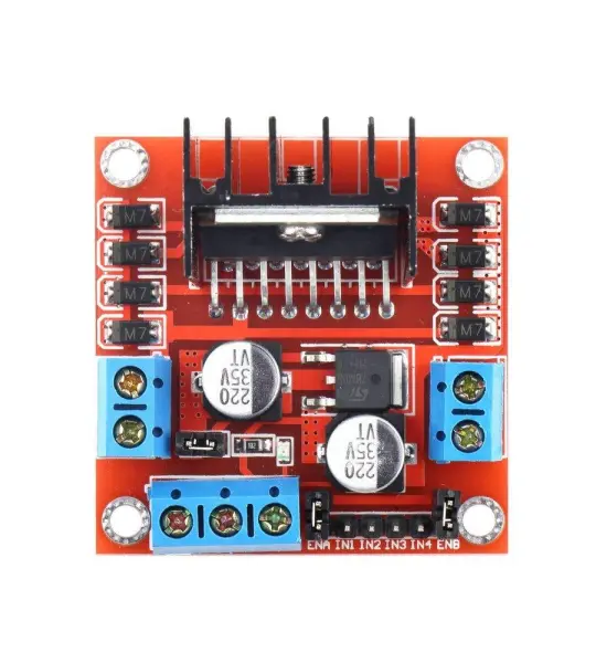
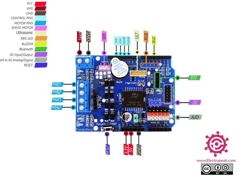
A half-bridge circuit is one of the simplest methods to control a DC motor. This method not only controls the motor direction, but also can be used for speed control. This shield is based on L298P IC.

The most important features are:

  • Control two DC motors simultaneously with voltage 4.8 to 24V and up to 2A current
  • Schottky diodes to protect against reverse motor voltage
  • Drive a servo motor with a dedicated voltage regulator
  • Buzzer to make sound
  • Bluetooth connections
  • 6 digital and analog pins with 5V and GND pins for easy connection
  • Special pins for connection to ultrasonic sensor

Control of two DC motors connections:

  • VMS: Module voltage
  • GND: Ground
  • MA1: Positive end for motor A
  • MA2: Negative end for motor A
  • MB1: Positive end for motor B
  • MB2: Negative end for motor B
  • PWMA: Speed control signal for motor A – This pin is connected to pin 10 of Arduino
  • PWMB: Speed control signal for motor B – This pin is connected to pin 11 of Arduino
  • ENA: Control signal for motor A – If HIGH, motor is in direct mode and if LOW, motor is rotating in reverse. This pin is connected to pin 12 of Arduino
  • ENB: Control signal for motor B – If HIGH, motor is in direct mode and if LOW, motor is rotating in reverse. This pin is connected to pin 13 of Arduino

Buzzer for make sound:

  • BUZ: Buzzer pin – This pin is connected to pin 4 of Arduino

Connection for control servo motor:

  • SER: PWM pin for control servo motor – This pin is connected to pin 9 of Arduino

Bluetooth connections:

  • BT2: Bluetooth Pins including +(3.3V) pins, (GND), RX (connected to D0) and TX (connected to D1)

Ultrasonic sensor connection:

  • ULT: connection pins to ultrasonic sensor including +(5V), (GND), Return (connected to D9) and Trigger (connected to D8)

RBG LED connection:

  • RGB: RGB: For connection to RGB LED including pins B (connected to D6), G (connected to D5) and R (connected to D3)

Other connections:

  • A/D: Analog and digital pins A0 to A5 for sensor and module use
  • D2: Digital pin 2 for sensor and module use
  • RS: Reset pin
  • GND: Ground
  • VCC: Board power supply – 3V, 5V

You can see the pinout of this module in the image below.

L298P Motor Driver Module Pinout

Add your review

Your email address will not be published. Required fields are marked *

Please login to write review!

Upload photos

Looks like there are no reviews yet.
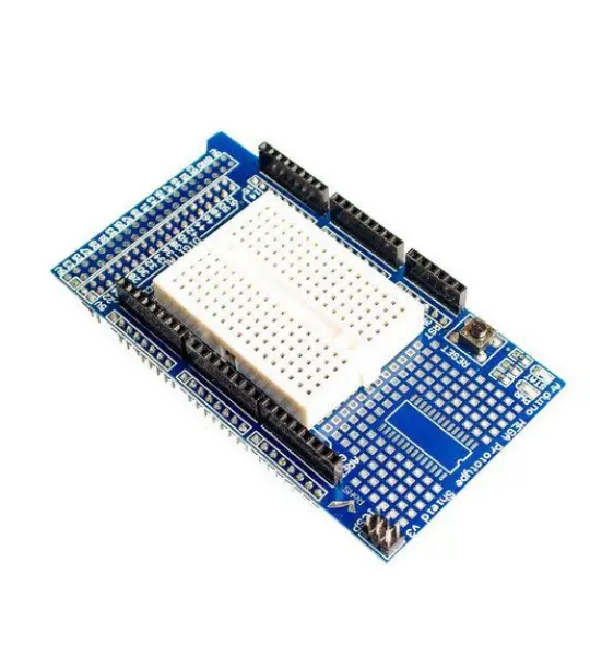
Related Products