+965 51122049

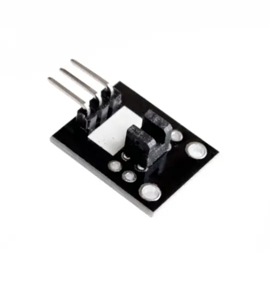
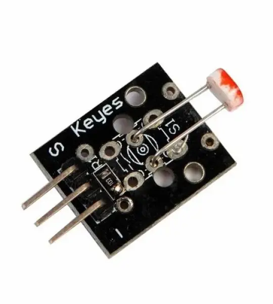
Optical broken module ( ARDUINO photo interrupter module )
If you view from the top like on the photo
Connect the module to the arduino as follows:
// Example code for KY-010


// photo interrupter module


int

	 Led =

	 13

	 ;

	// define LED Interface


int

	 buttonpin =

	 3

	;

	 // define the photo interrupter sensor interface


int

	 val ;

	// define numeric variables val


void

	 setup ()


{


  pinMode (

	Led,

	 OUTPUT)

	 ;

	// define LED as output interface


  pinMode (

	buttonpin,

	 INPUT)

	 ;

	// define the photo interrupter sensor output interface


}


void

	 loop ()


{


  val =

	 digitalRead (

	buttonpin)

	 ;

	// digital interface will be assigned a value of 3 to read val


  if

	 (

	val ==

	 HIGH)

	 // When the light sensor detects a signal is interrupted, LED flashes


  {


    digitalWrite (

	Led,

	 HIGH)

	;


  }


  else


  {


    digitalWrite (

	Led,

	 LOW)

	;


  }


}
Your email address will not be published. Required fields are marked *
Please login to write review!
Looks like there are no reviews yet.
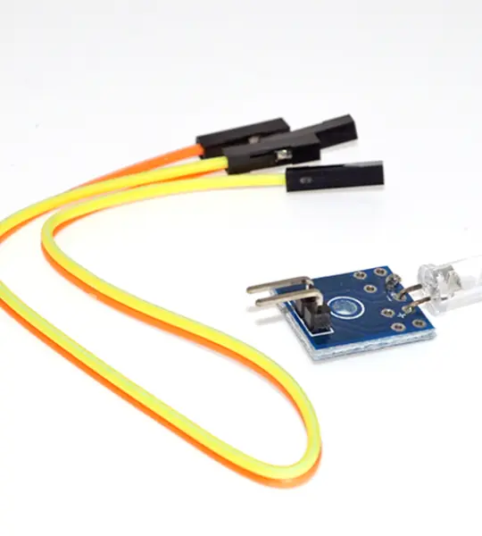
One Diode Light Brightness Detection Photosensitive Sensor with Wire
Photoresistor - Photosensitive resistor module