This module consists of a 5050 SMD LED and 4 male header pins. Use with limiting resistors to prevent LED burnout.
| Operating Voltage | 5V max Red 1.8V ~2.4V Green 2.8V ~ 3.6V Blue 2.8V ~ 3.6V |
| Forward Current | 20mA ~ 30mA |
| Operating Temperature | -25°C to 85°C [-13°F ~ 185°F] |
| Board Diemsions | 18.5mm x 15mm [0.728in x 0.591in] |
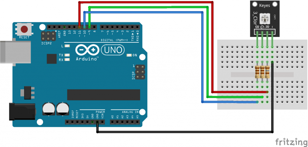
Connect the red pin (R) to Pin 9, the green pin (G) to pin 10, the blue pin (B) to pin 11 and finally the ground pin (-) to GND.
You must use resistors between the board and the Arduino to prevent LED burnout.
| KY-009 | Breadboard | Arduino |
|---|---|---|
| R | 180Ω resistor | Pin 9 |
| G | 110Ω resistor | Pin 10 |
| B | 110Ω resistor | Pin 11 |
| – | GND |

The following Arduino sketch will cycle through various colors by changing the PWM value on each of the three primary colors.
int redpin = 11; //select the pin for the red LED
int bluepin =10; // select the pin for the blue LED
int greenpin = 9;// select the pin for the green LED
int val;
void setup() {
 pinMode(redpin, OUTPUT);
 pinMode(bluepin, OUTPUT);
 pinMode(greenpin, OUTPUT);
 Serial.begin(9600);
}
void loop()
{
 for(val = 255; val > 0; val--)
 {
  analogWrite(redpin, val); //set PWM value for red
  analogWrite(bluepin, 255 - val); //set PWM value for blue
  analogWrite(greenpin, 128 - val); //set PWM value for green
  Serial.println(val); //print current value
  delay(1);
 }
 for(val = 0; val < 255; val++)
 {
  analogWrite(redpin, val);
  analogWrite(bluepin, 255 - val);
  analogWrite(greenpin, 128 - val);
  Serial.println(val);
  delay(1);
 }
}
Your email address will not be published. Required fields are marked *
Please login to write review!
Looks like there are no reviews yet.