Pin Number | Description |
NEGATIVE TERMINALS | |
1 | PIN1 is taken out from 4th COLUMN |
2 | PIN2 is taken out from 2nd COLUMN |
5 | PIN5 is taken out from 1st COLUMN |
7 | PIN7 is taken out from 3rd COLUMN |
8 | PIN8 is taken out from 6th COLUMN |
9 | PIN9 is taken out from 8th COLUMN |
12 | PIN12 is taken out from 5th COLUMN |
14 | PIN14 is taken out from 7th COLUMN |
POSITIVE TERMINALS | |
3 | PIN3 is taken out from 2nd ROW |
4 | PIN4 is taken out from 3rd ROW |
6 | PIN6 is taken out from 5th ROW |
10 | PIN10 is taken out from 4th ROW |
11 | PIN11 is taken out from 6th ROW |
13 | PIN13 is taken out from 1st ROW |
15 | PIN15 is taken out from 7th ROW |
16 | PIN16 is taken out from 8th ROW |
As given in above table, any 8x8 LED MATRIXwill have EIGHT POSITIVE TERMINALS and EIGHT NEGATIVE TERMINALS.
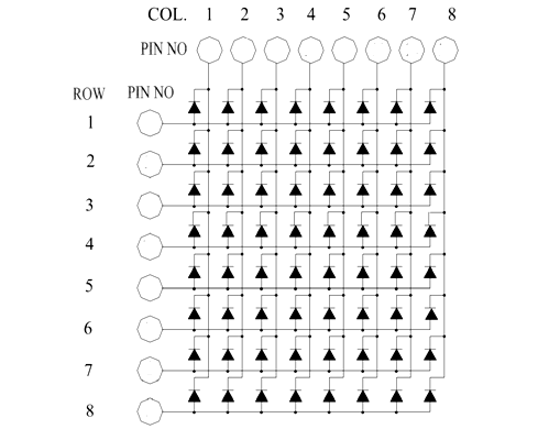
These 16 PINS are driven out from 64 LED SEGMENTS present in the MODULE. Those 64 SEGMENTS on the MODULE surface are the 64 LEDS arranged in MATRIX formation.
The internal structure of any LED MATRIX MODULE will be same and is shown below.

Note: More technical information can be found in the LED Matrix Datasheet linked at the bottom of this page.
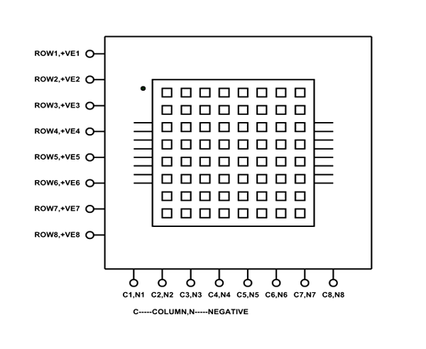
As shown above, the POSITIVE and NEGITIVE PINS of MATRIX MODULE are irregular and may lead to problems while controlling the LEDs. This issue becomes even more complex when choosing a different MODULE. The best way to solve these problems is rearrange the terminals based on FUNCTION of PIN instead of PIN NUMBER. After rearranging the PINS, we will have something as below.

As shown in figure, by rearranging the EIGHT ROWS or POSITIVE and EIGHT COLUMNS or NEGATIVE we can completely eliminate the problem of PIN CONFIGURATION. As every module will have same ROWS and COLUMN even if MODULE outlets are random.
Your email address will not be published. Required fields are marked *
Please login to write review!
Looks like there are no reviews yet.