Subscribe to the newsletter to receive updates about new products.

Welcome Engineers to our first application in our Arduino series, we will learn to ignite the LEDs.
Materials required:
What is LED?
An LED is an abbreviation of the initials of the word Light Emitting Diode, which means light emitting diode.Unlike the small bulbs that we use and work with most of the 6V we use in our project, LEDs have two different types of anodes and cathodes.The anode should be connected to the positive tension, ie, + uca, and the cathode to the negative tension, ie, to the ground or to the ground (GND, Ground).
Voltage, Current and Ohm Law
We know that various circuit elements operate at different voltages or voltages.Our Arduino card works with 5V voltage.This is a little different for our LED.The maximum current to pass through the LED should not exceed 20mA (milliampere = 1 in 1000 amps).We said that Arduino worked with 5V.The 5V value tells us the output voltage of the card.But the LED needs 20mA current.I think things got a little confused.There's no need to be scared!Everything has a solution.
If we connect our LED directly to Arduino, the maximum current that the card can supply through the LED will pass and the LED or card will be broken.For this we need a series resistor to our current limiting resistor LED.How will this resistance value be determined?Here's the equation we call Ohm's law:
V = i x R
In this equation, V represents the voltage, i is the current, and R is the resistance.If you would connect the LED that needs 20mA current to one of the pins that provide Arduino 5V output;
5V = 0.020A x R
We get the equation.If we are going to pull R from this equation, we have 250.This means that we need a resistance of 250 Ω (ohms) to use our LED with 5V voltage.It does not matter if we fix the exact value correctly, we can use the available 220 Ω resistor.
This theoretical knowledge is enough for now, Now we are preparing our Arduino program.
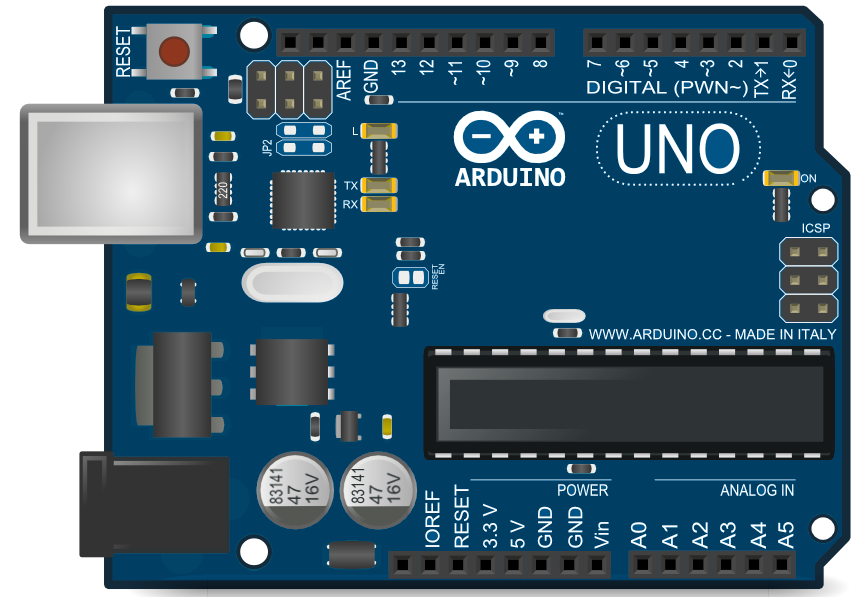
When we introduced Arduino in our first lesson, we mentioned that there is an LED connected to pine number 13 on the card.No extra resistance is needed to ignite this LED;The resistance is already present on the card.
We are opening our Arduino program.We follow the sequence below to open the sample program named "Blink":
File> Examples 01.Basics> Blink
modified 6 December 2016
by Eng
*/
// the setup function runs once when you press reset or power the
void setup() {
// initialize digital pin 13 as an output.
pinMode(13, OUTPUT);
}
// the loop function runs over and over again forever
void loop() {
digitalWrite(13, HIGH); // turn the LED on
delay(1000); // wait for a second
digitalWrite(13, LOW); // turn the LED off
delay(1000); // wait for a second
}
Let's examine this code together:
PinMode (13, OUTPUT);
This line sets the pin number 13 on the card to output.Input or output functions that we write at the end of the program can not use that pin if the pin to use is not set as output or input.
  DigitalWrite (13, HIGH);


 Delay (1000);


 DigitalWrite (13, LOW);


 Delay (1000);
This part firstly sets the pine number 13 to the HIGH logic level, ie 5V, 1000 milliseconds (equal to 1 second) without any action, and this time sets the piano number 13 to the logical LOW ie 0V or ground level.After doing this, the microcontroller waits for 1 second without any action due to the delay function.
By changing the delay of the delay commands in this code, we can change the on and off times of the LED.If we want to use another pin, all we need to do is replace the pin number in the pinMode and digitalWrite functions with the pin number we want to use.We do not forget a resistance series connection of 220 Ω to our LED!
EVA Electronics Co. Wish You All The Success.
In this application, we will check the DC motor speed using a BJT type transistor. Why do we need a transistor...
The LM35 temperature sensor is an analogue output temperature sensor that performs precise temperature measure...
Are you sure you want to remove this product from cart?