+965 51122049

Note: Complete technical details can be found in the L298 Datasheet linked at the bottom of this page.
Here are few areas where L298 is preferred:
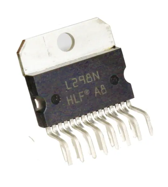
1. L298 is basically used where H- BRIDGE is required.
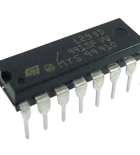
2. Where a high power motor driver is required. In the marked there are H-bridges like L293 which are used for low powered application while L298 is specially designed for high power applications.
3. Where current control and PWM operable single chip device is needed.
4. The chip is preferred when control unit can only provide TTL outputs
Also the chip does not need any additional components to be installed for operating.
For understanding the working of L298 IC, consider the simple circuit configuration shown below.
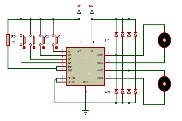
Here we are using one of H-BRIGES of l298 IC. As shown in circuit we have two push buttons Q1 and Q2 which act as controls inputs for bridge-A. These logic inputs are provided by Microcontroller or Microprocessor in application circuits. The four diodes are FLYBACK diodes used for protecting the IC form inductive voltage spikes. The enable pin is pulled high through a resistor so bridge-A will be functioning all the time. If it’s pulled to ground the bridge-A will be disabled no matter the input control logic.
After all the circuit is setup we need to press the buttons Q1 and Q2 to change the flow of current between pins OUT1 and OUT2. The logic control table is given as.
INPUTS | FUNCTION |
Q1=HIGH, Q2=LOW | Forward current |
Q1=LOW,Q2=HIGH | Reverse current |
Q1=Q2 | Fast MOTOR stop |
So if only Q1 is pressed, the current flows from OUT1 to OUT2. With that MOTOR rotates clock wise direction. If only Q2 is pressed, the current flows from OUT2 to OUT1. With that MOTOR rotates anti clock wise direction. If both buttons are pressed or released simultaneously the MOTOR comes to stop immediately. In this way we can control the motor rotation using L298 chip.
Your email address will not be published. Required fields are marked *
Please login to write review!
Looks like there are no reviews yet.