+965 51122049

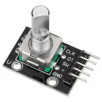
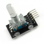
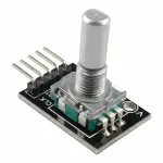
By rotating the rotary encoder can be counted in the positive direction and the reverse direction during rotation of the output pulse frequency, unlike rotary potentiometer counter, which Species rotation counts are not limited. With the buttons on the rotary encoder can be reset to its initial state, that starts counting from 0.
How it works: incremental encoder is a displacement of the rotary pulse signal is converted to a series of digital rotary sensors. These pulses are used to control Angular displacement. In Eltra angular displacement encoder conversion using a photoelectric scanning principle. Reading system of alternating light transmitting window and the window is not Consisting of radial indexing plate (code wheel) rotating basis, while being an infrared light source vertical irradiation light to the code disk image onto the receiving
On the surface. Receiver is covered with a diffraction grating, which has the same code disk window width. The receiver's job is to feel the rotation of the disc Resulting changes, and change the light into corresponding electrical changes. Then the low-level signals up to a higher level, and generates no interference Square pulse, which must be processed by electronic circuits. Reading systems typically employ a differential manner, about the same but the phase difference of the two waveforms Different by 180 ° compared to the signal in order to improve the quality and stability of the output signal. Reading is then the difference between the two signals formed on the basis, Thus eliminating the interference.
Incremental encoders give two-phase square wave, the phase difference between them 90 °, often referred to as A and B channels. One of the channels is given and speed-related Information, at the same time, by sequentially comparing two channel signals, the direction of rotation of the information obtained. There is also a special signal called Z or Zero channel, which gives the absolute zero position encoder, the signal is a square wave with the center line of channel A square wave coincide.
Clockwise counterclockwise
| A | B |
|---|---|
| 1 | 1 |
| 0 | 1 |
| 0 | 0 |
| 1 | 0 |
| 1 | 1 |
| 1 | 0 |
| 0 | 0 |
| 0 | 1 |
Incremental encoder accuracy depends on the mechanical and electrical two factors, these factors are: Raster indexing error, disc eccentricity, bearing eccentricity, e-reading Several means into the optical portion of the errors and inaccuracies. Determine the encoder resolution is measured in electrical degrees, the encoder accuracy depends Set the pulse encoder generates indexing. The following electrical degrees with a 360 ° rotation of the shaft to said machine, and rotation of the shaft must be a full week of Period. To know how much electrical equivalent of the mechanical angle of 360 degrees can be calculated with the following formula: Electrical 360 = Machine 360 ° / n ° pulses / revolution
Figure: A, B commutation signals
Encoder indexing error is the electrical angle of the unit two successive pulse maximum offset to represent. Error exists in any encoder, which Is caused by the aforementioned factors. Eltra encoder maximum error is ± 25 electrical degrees (declared in any condition), equivalent to the rated Offset values ± 7%, as the phase difference 90 ° (electrical) of the two channels of the maximum deviation ± 35 electrical degrees is equal to ± 10% deviation left Ratings Right.
UVW incremental encoder signals In addition to the conventional encoder, there are some other electrical output signal with integrated incremental encoder. And UVW signals The integrated incremental encoder that instance, it is usually applied to the AC servo motor feedback. These magnetic signals generally appear in the AC servo motor Machine, UVW through the simulation of the magnetic signal is generally of the original function and design. In Eltra encoder, these optical signals are UVW Methods of generating, and three square wave form, are offset from each other 120 °. In order to facilitate starting the motor, the control of the starter motor to be To these the correct signal. The UVW poles in the machine axis rotation pulses repeated many times, because they directly depend on the connected electrical Machine number of poles, and for 6 or more pole motor UVW signal.
int


	 redPin =


	 2


	;


int


	 yellowPin =


	 3


	;


int


	 greenPin =


	 4


	;


int


	 aPin =


	 6


	;


int


	 bPin =


	 7


	;


int


	 buttonPin =


	 5


	;


int


	 state =


	 0


	;


int


	 longPeriod =


	 5000


	;


	 // Time at green or red


int


	 shortPeriod =


	 700


	;


	 // Time period when changing


int


	 targetCount =


	 shortPeriod;


int


	 count =


	 0


	;


void


	 setup ()


{


  pinMode (


	aPin,


	 INPUT)


	;


  pinMode (


	bPin,


	 INPUT)


	;


  pinMode (


	buttonPin,


	 INPUT)


	;


  pinMode (


	redPin,


	 OUTPUT)


	;


  pinMode (


	yellowPin,


	 OUTPUT)


	;


  pinMode (


	greenPin,


	 OUTPUT)


	;


}


void


	 loop ()


{


  count++;


  if


	 (


	digitalRead (


	buttonPin))


  {


    setLights (


	HIGH,


	 HIGH,


	 HIGH)


	;


  }


  else


  {


    int


	 change =


	 getEncoderTurn ()


	;


    int


	 newPeriod =


	 longPeriod +


	 (


	change *


	 1000


	)


	;


    if


	 (


	newPeriod  >=


	 1000


	 &&


	 newPeriod <=


	 10000


	)


    {


      longPeriod =


	 newPeriod;


    }


    if


	 (


	count>


	 targetCount)


    {


      setState ()


	;


      count =


	 0


	;


    }


  }


  delay (


	1


	)


	;


}


int


	 getEncoderTurn ()


{


  // Return -1, 0, or +1


  static


	 int


	 oldA =


	 LOW;


  static


	 int


	 oldB =


	 LOW;


  int


	 result =


	 0


	;


  int


	 newA =


	 digitalRead (


	aPin)


	;


  int


	 newB =


	 digitalRead (


	bPin)


	;


  if


	 (


	newA !=


	 oldA ||


	 newB !=


	 oldB)


  {


    //Something has changed


    if


	 (


	oldA ==


	 LOW &&


	 newA ==


	 HIGH)


    {


      result =


	 -


	 (


	oldB *


	 2


	 -


	 1


	)


	;


    }


  }


  oldA =


	 newA;


  oldB =


	 newB;


  return


	 result;


}


int


	 setState ()


{


  if


	 (


	state ==


	 0


	)


  {


    setLights (


	HIGH,


	 LOW,


	 LOW)


	;


    targetCount =


	 longPeriod;


    state =


	 1


	;


  }


  else


	 if


	 (


	state ==


	 1


	)


  {


    setLights (


	HIGH,


	 HIGH,


	 LOW)


	;


    targetCount =


	 shortPeriod;


    state =


	 2


	;


  }


  else


	 if


	 (


	state ==


	 2


	)


  {


    setLights (


	LOW,


	 LOW,


	 HIGH)


	;


    targetCount =


	 longPeriod;


    state =


	 3


	;


  }


  else


	 if


	 (


	state ==


	 3


	)


  {


    setLights (


	LOW,


	 HIGH,


	 LOW)


	;


    targetCount =


	 shortPeriod;


    state =


	 0


	;


  }


}


void


	 setLights (


	int


	 red,


	 int


	 yellow,


	 int


	 green)


{


  digitalWrite (


	redPin,


	 red)


	;


  digitalWrite (


	yellowPin,


	 yellow)


	;


  digitalWrite (


	greenPin,


	 green)


	;


}
Your email address will not be published. Required fields are marked *
Please login to write review!
Looks like there are no reviews yet.
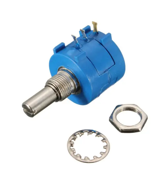
3590S 100K Precision Multi turn Adjustable Potentiometer