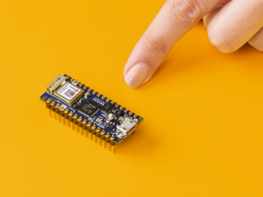

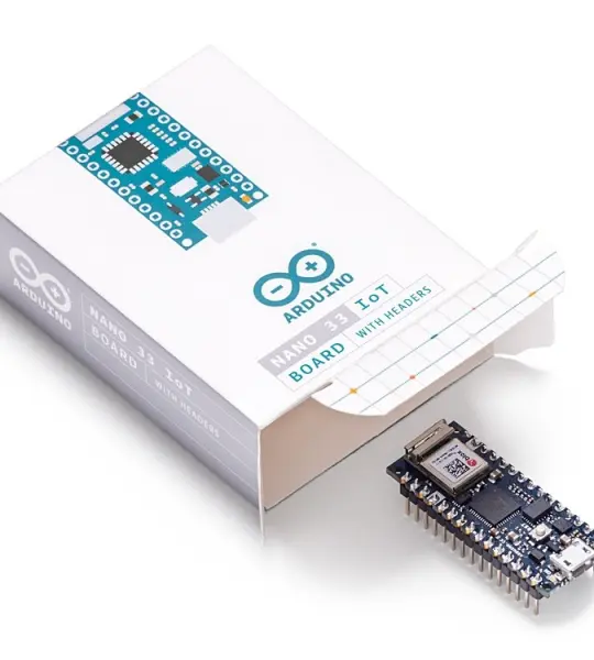
The Arduino Nano 33 IoT is the easiest and cheapest point of entry to enhance existing devices (and creating new ones) to be part of the IoT and designing pico-network applications. Whether you are looking at building a sensor network connected to your office or home router, or if you want to create a Bluetooth® Low Energy device sending data to a cellphone, the Nano 33 IoT is your one-stop-solution for many of the basic IoT application scenarios.
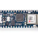
The board's main processor is a low power Arm® Cortex®-M0 32-bit SAMD21. The WiFi and Bluetooth® connectivity is performed with a module from u-blox, the NINA-W10, a low power chipset operating in the 2.4GHz range. On top of those, secure communication is ensured through the Microchip® ECC608 crypto chip. Besides that, you can find a 6 axis IMU, what makes this board perfect for simple vibration alarm systems, pedometers, relative positioning of robots, etc.
WiFi and Arduino IoT Cloud
At Arduino we have made connecting to a WiFi network as easy as getting an LED to blink. You can get your board to connect to any kind of existing WiFi network, or use it to create your own Arduino Access Point. The specific set of examples we provide for the Nano 33 IoT can be consulted at the WiFiNINA library reference page.
It is also possible to connect your board to different Cloud services, Arduino's own among others. Here some examples on how to get the Arduino boards to connect to:
Arduino's own IoT Cloud: Arduino's IoT Cloud is a simple and fast way to ensure secure communication for all of your connected Things. Check it out here
Blynk: a simple project from our community connecting to Blynk to operate your board from a phone with little code
IFTTT: see an in-depth case of building a smart plug connected to IFTTT
AWS IoT Core: we made this example on how to connect to Amazon Web Services
Azure: visit this github repository explaining how to connect a temperature sensor to Azure's Cloud
Firebase: you want to connect to Google's Firebase, this Arduino library will show you how
Note: while most of the above-shown examples are running on the MKR WiFi 1010, both boards have the same processor and wireless chipset, which means it will be possible to replicate them with the Nano 33 IoT.
Bluetooth® and Bluetooth® Low Energy
The communications chipset on the Nano 33 IoT can be both a Bluetooth® and Bluetooth® Low Energy client and host device. Something pretty unique in the world of microcontroller platforms. If you want to see how easy it is to create a Bluetooth® central or a peripheral device, explore the examples at our ArduinoBLE library.
We Make it Open for you to Hack Along
The Nano 33 IoT is a dual processor device that invites for experimentation. Hacking the WiFiNINA module allows you to, for example, make use of both WiFi and Bluetooth® and Bluetooth® Low Energy at once on the board. Yet another possibility is having a super-lightweight version of linux running on the module, while the main microcontroller controls low level devices like motors, or screens. These experimental techniques, require advanced hacking on your side. They are possible via modifying the module's firmware that you can find at our github repositories.
BEWARE: this kind of hacking breaks the certification of your WiFiNINA module, do it at your own risk.
Related Boards
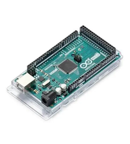
If you are looking at upgrading from previous Arduino designs, or if you are just interested in boards with similar functionality, at Arduino you can find:
Arduino MKR WiFi 1010: the Pro version of the Nano 33 IoT, lacks the accelerometer, but includes a battery charger, and the Arduino Eslov connector for external I2C boards. Read more here.
Arduino Uno WiFi rev2: the education version of the MKR WiFi 1010, with USB-B connector and embedded accelerometer. Read more here.
MKR WiFi 1000: can only run WiFi applications, as it includes a different chipset than the Nano 33 IoT. Read more about it here.
Arduino IoT Cloud Compatible
![]()
Use your MKR board on Arduino's IoT Cloud, a simple and fast way to ensure secure communication for all of your connected Things.
TRY THE ARDUINO IOT CLOUD FOR FREE
Getting Started
The Getting Started section contains all the information you need to configure your board, use the Arduino Software (IDE), and start tinkering with coding and electronics.
Need Help?
Check the Arduino Forum for questions about the Arduino Language, or how to make your own Projects with Arduino. Need any help with your board please get in touch with the official Arduino User Support as explained in our Contact Us page.
Warranty
You can find here your board warranty information.