+965 51122049

Here’s a summary of the ESP32-C3 technical specifications:
You can also take a look at the following table:
Microcontroller (processor) | Espressif ESP32-C3 (32-RISC-V single-core, up to 160 MHz) |
Flash Memory | 4 MB (onboard SPI flash) |
SRAM | 400 KB |
ROM | 384 KB |
Wi-Fi | 802.11 b/g/n, 2.4 GHz, up to 150 Mbps |
Bluetooth | Bluetooth 5.0 LE |
GPIO Pins | 11 accessible GPIOs |
Analog Inputs (ADC) | 2 × 12-bit SAR ADCs, up to 6 channels |
PWM Channels | 6 channels |
SPI | 3 × SPI interfaces (SPI0, SPI1 reserved) |
I2C | 1 × I2C interface |
UART | 2 × UART interfaces |
I2S | 1 × I2S interface |
USB Interface | USB-C, supports USB CDC |
Power Supply | 5V via USB-C or 3.3V–6V via VIN (5V) pin; onboard 3.3V regulator (up to 500 mA) |
Operating Voltage | 3.3V (logic level for GPIOs) |
Deep Sleep Mode | 43uA |
Buttons | 1 × Reset button, 1 × Boot button (GPIO9) |
LED | 1 × onboard LED (on GPIO8, active low) |
Programming | Arduino IDE, ESP-IDF, MicroPython, PlatformIO/pioarduino |
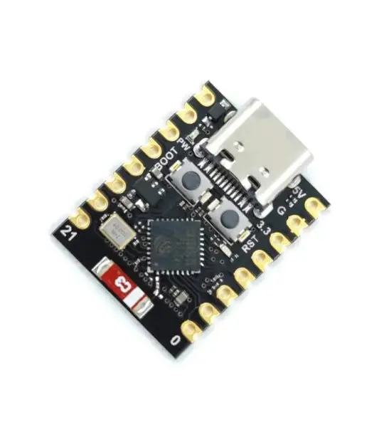
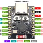
The following picture shows the pinout for the ESP32-C3 Super Mini board. Please note that the pinout can change slightly depending on the manufacturer. So, double-check the pinout with the pin mapping on the silkscreen of your board.

The following table describes the pin mapping and its functions.
Pin | Function |
3V3 | 3.3V output/input (outputs 3.3V from the onboard regulator, or it is a input for external 3.3V power supply) |
5V | 5V input/output (connects to the USB-C 5V or external 5V supply) |
GND | GND pin |
GPIO 0 | General-purpose I/O, ADC1, PWM |
GPIO 1 | General-purpose I/O, ADC1, PWM |
GPIO 2 | General-purpose I/O ADC1, Strapping Pin (Boot Mode) (avoid for general use) |
GPIO 3 | General-purpose I/O, PWM |
GPIO 4 | General-purpose I/O, PWM, default SPI SCK pin |
GPIO 5 | General-purpose I/O, PWM, default SPI MISO pin |
GPIO 6 | General-purpose I/O, PWM, default SPI MOSI pin |
GPIO 7 | General-purpose I/O, PWM, default SPI SS pin |
GPIO 8 | Connected to the onboard LED (active low); Strapping Pin (avoid for general use); Default I2C SDA pin |
GPIO 9 | Connected to BOOT Button (LOW to enter bootloader), Strapping Pin (avoid for general use) Default I2C SCL pin |
GPIO 10 | General-purpose I/O, PWM |
GPIO 20 | General-purpose I/O, PWM, default UART RX Pin |
GPIO 21 | General-purpose I/O, PWM, default UART TX Pin |
Strapping Pins
You can still use the strapping pins in your projects, however, you need to take into account the fluctuation of the state of these GPIOs when the ESP32 resets or enters into bootloader mode.
Power Pins
When it comes to power pins, you have one 5V, one 3V3, and a GND pin.
The 3V3 pin provides 3.3V from the onboard regulator or accepts 3.3V from an external power source. Similarly, the 5V pin, can be used for input to power the board, or it outputs 5V from the USB power supply.
PWM
All general-purpose GPIOs can output PWM signals.
Analog (ADC) Pins
GPIOs 0, 1, 2, 3, 4, and 5 support analog reading:
UART, I2C, and PWM
Due to the ESP32 multiplexing feature, the UART, SPI, and I2C interfaces can be assigned to nearly any GPIO.
However, when using Arduino IDE, and assuming you’re selecting the ESP32 C3 board in the Boards menu, it will assume the following pins as defaults:
For more information about the board, you can check its datasheet in the link below:
Your email address will not be published. Required fields are marked *
Please login to write review!
Looks like there are no reviews yet.
arduino Nano V3.0 ATmega328P 5V 16MHz CH340C Type C
Arduino is an open-source physical computing platform based on a simple i/o board and a development environment that implements the Processing/ Wiring language.
ARDUINO YUN REV 2 ABX00020 ATmega32U4 Development Board