+965 51122049

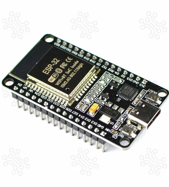
ESP32S Development Board Devkit v1 USB Type C
The ESP32 Devkit V1 by Espressif Systems is currently the smallest microcontroller series in the world, featuring built-in WiFi and Bluetooth simultaneously, making it ideal for IoT projects or small electronic applications.
When comparing the ESP32 to the Arduino , Atmel , or PIC , you'll find that the ESP32 Devkit V1 offers more pins, a faster processor, and superior overall performance. Some even compare the Raspberry Pi to the ESP32, but the ESP32 is smaller, cheaper, consumes less power, and is more suitable for compact projects.
If you’re just getting started, check out our ESP32 Tutorials in Bangla .
| Parameter | Details |
|---|---|
| Microcontroller | ESP-WROOM-32 |
| Processor | Xtensa dual-core 32-bit LX6 |
| Clock Speed | 240 MHz |
| RAM | 520 KB SRAM, 448 KB ROM, 16 KB SRAM in RTC |
| Flash Memory | 4 MB |
| WiFi | 802.11b/g/n |
| Bluetooth | V4.2 |
| GPIOs | 25 |
| Antenna | On-board PCB antenna |
| Programming Port | USB Type-C |
| USB to UART | CP2102 |
| Dimensions | 50 × 29 mm (±2) |
All of the 25 GPIOs, including 15 ADC, 2 UART, 25 PWM, 2 DAC, 3 SPI, 1 I2C, 2 I2S, and 9 Touch functionality. 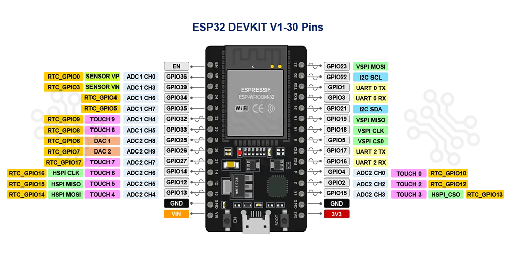
| Pin | GPIO | Alternate Pin Function | Safe | Remarks |
|---|---|---|---|---|
| 1 | EN / RESET | |||
| 2 | GPIO36 | VP / ADC1_0 | ⚠️ | Input only |
| 3 | GPIO39 | VN / ADC1_3 | ⚠️ | Input only |
| 4 | GPIO34 | ADC1_6 | ⚠️ | Input only |
| 5 | GPIO35 | ADC1_7 | ⚠️ | Input only |
| 6 | GPIO32 | ADC1_4 / Touch9 | ✔️ | |
| 7 | GPIO33 | ADC1_5 / Touch8 | ✔️ | |
| 8 | GPIO25 | ADC2_8 / DAC1 | ✔️ | |
| 9 | GPIO26 | ADC2_9 / DAC2 | ✔️ | |
| 10 | GPIO27 | ADC2_7 / Touch7 | ✔️ | |
| 11 | GPIO14 | ADC2_6 / Touch6 / HSPI_CLK | ✔️ | |
| 12 | GPIO12 | ADC2_5 / Touch5 / HSPI_MISO | ⚠️ | Must be LOW during boot |
| 13 | GPIO13 | ADC2_4 / Touch4 / HSPI_MOSI | ✔️ | |
| 14 | GND | — | ||
| 15 | VIN | — | 4.8V < VIN < 12V | |
| 16 | 3.3V | — | 600mA | |
| 17 | GND | — | ||
| 18 | GPIO15 | ADC2_3 / Touch3 / HSPI_CS | ⚠️ | Must be HIGH during boot, prevents startup log if pulled LOW |
| 19 | GPIO2 | ADC2_2 / Touch2 / CS | ⚠️ | Must be LOW during boot and connected to onboard LED |
| 20 | GPIO4 | ADC2_0 / Touch0 | ✔️ | |
| 21 | GPIO16 | U2_RXD | ✔️ | |
| 22 | GPIO17 | U2_TXD | ✔️ | |
| 23 | GPIO5 | VSPI_CS | ⚠️ | Must be HIGH during boot |
| 24 | GPIO18 | SCK | ✔️ | |
| 25 | GPIO19 | VSPI_MISO | ✔️ | |
| 26 | GPIO21 | SDA | ✔️ | |
| 27 | GPIO22 | SCL | ✔️ | |
| 28 | GPIO23 | VSPI_MOSI | ✔️ | |
| 29 | TX0 | UART0_TX | ⚠️ | Used for programming |
| 30 | RX0 | UART0_RX | ⚠️ | Used for programming |
The ESP32 Dev Board V1 features a positive voltage regulator, specifically the AMS1117-3.3, which enables operation with external power sources. This configuration eliminates the need to keep the board connected to your computer for power. When powered via the VIN pin, the input voltage is passed through the regulator, which then converts it to a stable 3.3V output, providing power to the board’s various power rails.
According to the datasheet, the AMS1117-3.3 can safely operate with input voltages ranging from 4.8V to 12V. However, higher input voltages may necessitate additional heat dissipation to prevent overheating. For optimal performance and thermal management, it is recommended to use an input voltage in the range of 5V to 6V.
For more information on the ESP32 power control system, we invite you to explore our Bengali tutorial titled Powering ESP32 with External Power .
The ESP32 can be programmed using various platforms, such as the Espressif IDE , Thonny IDE , PlatformIO with Visual Studio Code , and the Arduino IDE . A quick search on Google will yield numerous online tutorials covering these platforms. Some notable examples include:
Once you have installed ESP Boards via the Board Manager of Arduino IDE, you can find various example projects, including Blink, Digital Read Serial, Analog Read Serial, Button, PWM, WiFI Web Server, WiFi Web Client, etc.
From the Arduino IDE, go to Tools > Board and select esp32 > ESP32 Dev Module. Once you have the ESP32 board chosen, go to File > Examples. Inside that folder, you will find various example sketches for different functionalities like WiFi, Bluetooth, Sensors, and more.
TechShopBD offers up to one year of warranty and replacement support for its products, depending on the supplier(s) and product(s). The specific warranty duration for each product can be found on the respective product page. To be eligible for warranty and replacement support, customers must agree to our terms and conditions .
Note: This item is non-returnable. If this item arrives damaged or is not functioning properly, please don’t hesitate to contact us to determine if further action is required.
Our engineers are available to assist you. If you have any queries, please leave a comment below or call 09678110110 from 09:00 am to 06:00 pm (7 days a week). You can also reach us via WhatsApp or Facebook Inbox
The ESP32 Development Board DEVKIT V1 is your go-to tool for evaluating the powerful ESP-WROOM-32 module. Packed with Wi-Fi and Bluetooth capabilities, this board, powered by the ESP32 microcontroller, enables seamless connectivity and high-performance IoT applications—all within a single chip. Whether you're building wireless solutions, smart devices, or experimenting with your next big project, this board delivers endless possibilities.
2.4 GHz Wi-Fi
Bluetooth 4.2
Flash Memory: 4 MByte (32Mbit) SPI Flash
ROM: 448 KB
SRAM: 520 KB
RTC SRAM: 16 KB
User LED
Power LED
The DEVKIT V1 can be powered via:.
USB Type-C Connector For USB-based power supply and programming.
Vin Pin: For direct external DC power input (6V to 20V).
⚠️ Important Note: Avoid input voltages above 12V to prevent overheating or damage to the onboard voltage regulator. The recommended range is 7V–12V.
Your email address will not be published. Required fields are marked *
Please login to write review!
Looks like there are no reviews yet.
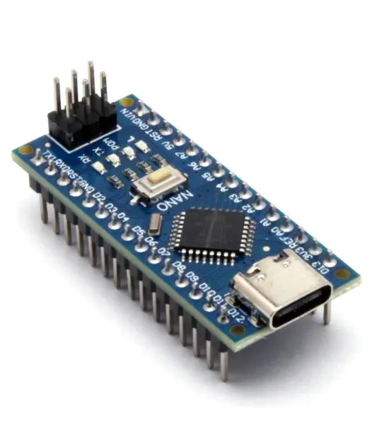
arduino Nano V3.0 ATmega328P 5V 16MHz CH340C Type C
Arduino is an open-source physical computing platform based on a simple i/o board and a development environment that implements the Processing/ Wiring language.
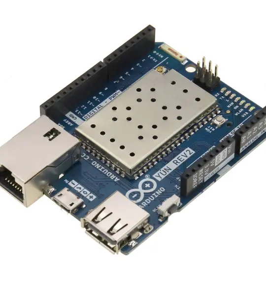
ARDUINO YUN REV 2 ABX00020 ATmega32U4 Development Board